When I started learning how to design functional parts, it didn't take long for me to have to put a couple of those together and create a functional system. I vaguely remembered the term 'tolerance' from the forums I had been tracking, so that's what I typed into google to kick off my rabbit trail of research.
I'll be honest, it was a little confusing. Not because it was overly complex, but because there were so many differing and contradicting opinions and pieces of information. It suddenly seemed like quite a daunting task... I persisted, however, with my research and finally stumbled upon an article (I wish I could remember which one) that mentioned clearance.
💡Light bulb! 💡
In reading the article I realised that so many people had been misusing the word tolerance, whether it was due to lack of knowledge or just trying to sound smart (none of us would every be found guilty of this... would we 🫢). A lot of people used tolerance as a blanket term to describe any interface between parts, without even mentioning crucial terms like allowance and clearance. That meant a beginner designer, like I was, trying to develop good design practices was easily led astray.
What are these, how do they differ and when to use them?
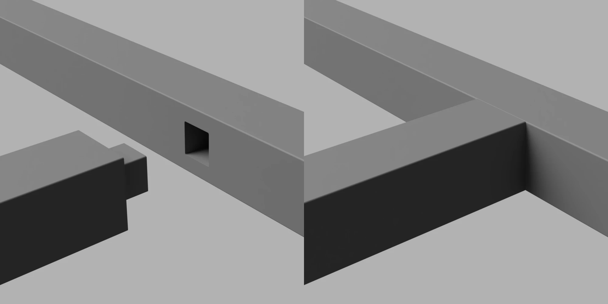
Keep the following image in mind because I'll use it as an example in the coming sections. The image depicts an object that is intended to be joined to another object via a square cut-out (some of you smart cookies might recognize this as a Mortise and Tenon join).

Tolerance
I'll start with tolerance because that is what us 3D enthusiasts come across most often, and I'll start with an example: I have designed the square join to be 10mm x 10mm x 10mm, then have printed the part on an entry level 3D printer. We get the vernier callipers out and we check the distance between two opposite faces on the cube, it measures at 10.2mm. Okay cool, that's pretty close to the designed values so we're off to a good start. We move the callipers 5mm along those faces and, hang on, now we are measuring 9.9mm. We are measuring the distance between the same faces in two different positions, shouldn't these measurements be the same? Is there something wrong with my printer?
Well, there (probably) isn't anything wrong with the printer, and this difference is a natural and omnipresent phenomenon called tolerance. See tolerance refers to the precision of a parts dimensions, or how close all these measurements are too each other, and is typically found as a plus/minus percentage of the actual measurement.
It's essential to understand that tolerance does not affect accuracy; it affects precision. This is an important distinction. See the image below for a visual representation of the difference between precision and accuracy.

** Image taken 03/03/2024 from What Is the Difference Between Accuracy and Precision? (sciencenotes.org) by Todd Helmenstine, 14/04/2014 **
Every printer will have a tolerance, in fact every manufacturing machine will also have a tolerance, and it'll depend on a bunch of different factors: nozzle size, structure rigidity, flow consistency and many more.
Using the Terminology - Tolerance
The correct use of the term tolerance may be:
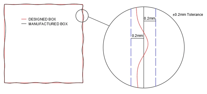
With the printer at my disposal, and how it is tuned at the moment, I can print that part with a ±0.2mm tolerance. That means for a part that is 10mm wide, you may measure down to 9.8mm and up to 10.2mm between the faces.
See the image below for a visual aid of what a 0.2mm tolerance might look like on a 10mm x 10mm part. Noticing that the red box indicated the designed part, which is exactly square, and the black box is indicative of a physical, manufactured part.

Allowance
Right, we know what tolerance is, what is allowance? Allowance is a design feature.
If we have a 10mm diameter hole in the cube, and we want to insert a rod into it, shouldn't that rod also be 10mm? Absolutely not!
Due to tolerances and systematic inaccuracies of the printer, a 10mm radius rod will not fit into a 10mm radius hole. There are two main reasons for this: (1) You can't design fitting parts the exact same dimensions. This does not leave room for things like trace width due to nozzle size, material expansion and shrinkage etc. (2) In one direction you might measure the diameter of the hole on the physical print as 10.1mm. Slide the callipers down the faces a bit and all of a sudden the measurement is now 9.9mm (does this sound familiar? It should!).
So if the smallest diameter measured of the hole is 9.9mm, a rod designed to be 10mm in diameter will not fit. Nothing fancy about that. To make the rod fit, you should include in your design a gap between the parts, this designed gap is allowance.
An allowance can be designed in to a part in a couple of ways, one of the most common of which (and my personal favourite method) is offsetting the faces of either the male or female component, or ever both.
Using the Terminology - Allowance
The correct use of the term allowance may look something like:
'I have designed the part with an allowance of 0.15mm. I have achieved this by offsetting the faces of the female component by 0.15mm.'

Clearance
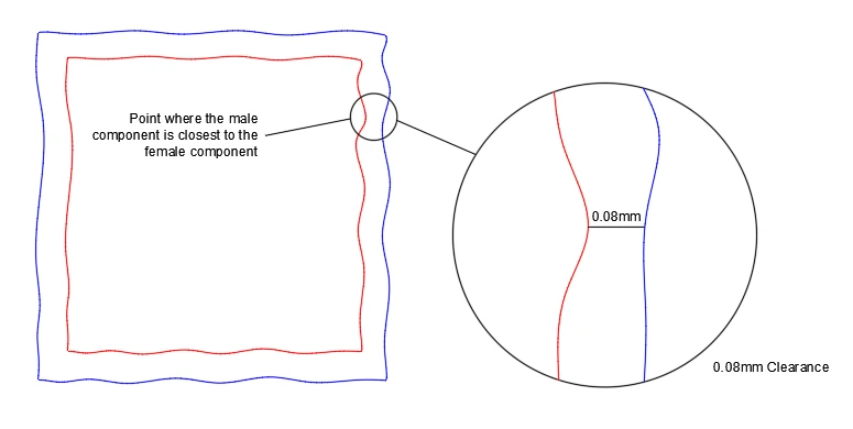
Now this is where things can sometimes get a little tricky, but fear not because it doesn't have to be that way. Technically, clearance is defined as the distance between the smallest gap of the maximum material of the pieces. It's a bit of a mouthful, I know, so I'll spell it out with help of the below diagram.

Remember, the manufactured parts are not perfectly square due to tolerances, systematic errors etc.
When looking at these parts, clearance can be identified at the point where the male and female parts are closest together, and the clearance of the part is the distance between the male and female components at this point.Here you can see that there is a distance of 0.08mm at the point where the male and female parts are closest. This part has a clearance of 0.0
8mm.
🧊Using the Terminology - Clearance🧊
You might here clearance be used like this:
'The manufactured/printed part has a clearance of 0.08mm.'
All the terms together
The 10mm x 10mm x 10mm join may have been designed with a 0.15mm allowance, and the print capability might have only reached a precision of ±0.035mm, so the part has a ±0.035mm tolerance. The smallest gap between the parts is likely to be as small as 0.07mm, so there may be as low as a 0.07mm clearance.
In practise the clearance isn't necessarily the largest measurement of the male component and the smallest measurement of the female component, but it is a good and convenient value to use for estimations and design exercises.
➡️Bonus Term - Interference
There is another term that I'll mention briefly, but I won't go into much detail about it because it is less commonly talked about in 3D printing circles; the term is interference. I mention it here because the smaller you design the allowance to be, the smaller the clearance will be. If the allowance is too small, the parts will start to overlap and the parts will interfere with rather than clear each other. The amount they overlap by is coined as interference.
Summary
Now that we have an understanding of these terms, and how these terms describe real world phenomena, we can summarize as the following:
🔸Tolerance is a natural phenomenon. It is inherent in every manufacturing method, for every material, on any object that is being created. Tolerance can be minimised by fine tuning, calibrations etc. but a tolerance is not part of the design. A larger tolerance indicates less precision.
🔹Allowance is part of the design. When trying to make parts fit together, allowances are designed between mating faces and features so that when the item is manufactured, even with it's systematic and random anomalies, the parts will still fit together and the system will work as it should.
🔺Clearance the distance between the mating parts, at the point where the mating parts are closest to each other. As long as this number is positive, the parts should fit together. The larger the clearance, the more the parts can move, which might be handy for things like hinges etc.
These terms are crucial for designing things like thread, gears, clips, inserts. Pretty much any system that involves parts working together.
I know most of you likely know this already, or account for these things naturally anyway, but I hope this helps someone who is researching how to design a tolerance ❌, where they should be asking how to make allowances to account for tolerances ✅ (and other aspects)!
Happy designing my fellow enthusiasts!
ShapeMaven
